#057 — Hard Drive POV Clock
A hard drive platter spins at 7200 RPM. Mount an LED, strobe it in sync, and persistence of vision turns it into a clock.
Ratings
🧪 What Is It?
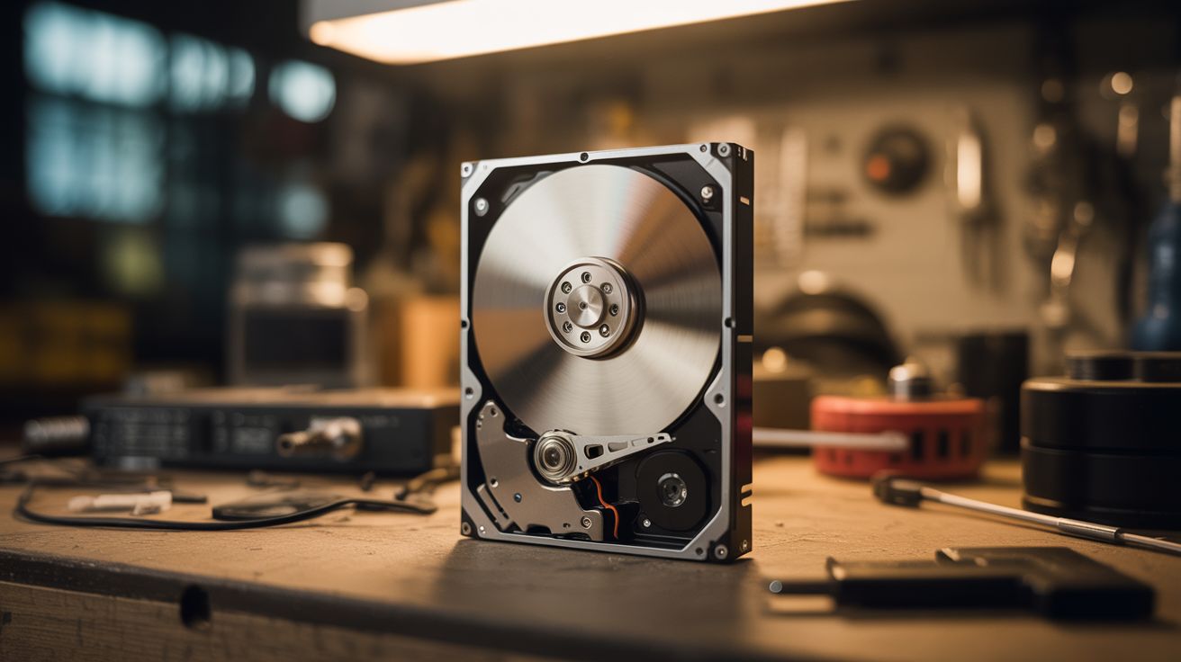
Hard drive platters spin at exactly 7200 RPM (or 5400 on some drives) — incredibly consistent, motor-controlled precision. That means each revolution takes exactly 8.33 milliseconds. Mount an LED on the read/write arm or on a bracket above the platter, use the drive's index pulse (one signal per revolution) to synchronize strobing, and persistence of vision does the rest. By flashing the LED at precise microsecond intervals during each revolution, you can draw clock hands, numbers, or any pattern that appears to float on the spinning platter. The result is a clock where the display literally doesn't exist — it's just light and timing.
🧰 Ingredients
- Dead hard drive with working spindle motor — 3.5" 7200 RPM preferred (e-waste bin)
- Arduino Nano or similar microcontroller (~$5, electronics supplier)
- RGB LED or small LED strip — SMD LEDs work best for resolution (electronics supplier)
- Hall effect sensor or IR sensor — for detecting platter position (~$1, electronics supplier)
- Small magnet — if using Hall effect sensor, glue to platter edge (hardware store)
- 12V power supply — to spin the HDD motor (old PC power supply works)
- Thin hookup wire (electronics supplier)
- Soldering iron + solder (workshop)
- Torx T8 screwdriver (hardware store)
- RTC module (DS3231) — for accurate timekeeping (~$2, electronics supplier)
🔨 Build Steps
- Open the hard drive and remove the top cover. Keep the spindle motor and platters intact — you need the motor to spin. Remove the read/write arm assembly (heads, arm, voice coil) to make space.
- Test the spindle motor. HDD motors are 3-phase brushless DC motors. You can spin them using an ESC (electronic speed controller) from the RC hobby world, or use a dedicated HDD motor driver. Connect 12V through the ESC and confirm the platter spins up smoothly.
- Install the position sensor. Glue a small magnet to the edge of the platter (or use the existing index hole if your drive has one). Mount a Hall effect sensor on the drive frame so it triggers once per revolution. This gives you a consistent "zero position" reference pulse.
- Mount the LED. Attach a small LED (or short LED strip for wider display) to a bracket positioned just above the platter surface, pointing down. The LED should be near the outer edge for maximum display radius. Keep wires tidy and secured so they don't contact the spinning platter.
- Wire the Arduino. Connect the Hall effect sensor to an interrupt pin on the Arduino. Connect the LED(s) to digital output pins. Connect the RTC module via I2C for accurate timekeeping.
- Write the timing code. In the interrupt handler, record the timestamp of each index pulse. Calculate the exact revolution period. Divide each revolution into angular segments (e.g., 360 segments for 1-degree resolution). For each segment, determine whether the LED should be on or off based on what part of the clock face that angle represents.
- Draw clock hands. Calculate hour, minute, and second hand positions from the RTC time. Light the LED when the platter's angular position matches a hand's position. Second hand = thin line (1-2 segments), minute hand = medium, hour hand = thick.
- Add numerals. Define pixel patterns for numbers 1-12 at their correct angular positions around the dial. Flash the LED in the appropriate pattern as the platter sweeps past each number's position. Start simple with tick marks before attempting full numerals.
- Calibrate and fine-tune. The display may appear to drift or wobble if timing is slightly off. Adjust the segment timing until the display is stable. Temperature changes can slightly affect motor speed, so recalibrate the period every few revolutions using the index pulse.
- Build an enclosure. The open spinning platter is mesmerizing but exposed. Consider a clear acrylic cover for dust protection while keeping full visibility. Add a dark background behind the platter to improve contrast.
⚠️ Safety Notes
- The platter spins at 7200 RPM. Never touch it while spinning — it will cut skin or catch loose clothing/hair. Keep fingers, cables, and tools clear.
- Hard drive magnets are brutally strong. When removing the voice coil assembly, they can snap together and crush fingertips. Pry them apart carefully with a flathead screwdriver.
- The LED strobe effect can trigger photosensitive epilepsy in susceptible individuals. Do not stare directly at the strobing display for extended periods.