#140 — EMF Ghost Detector
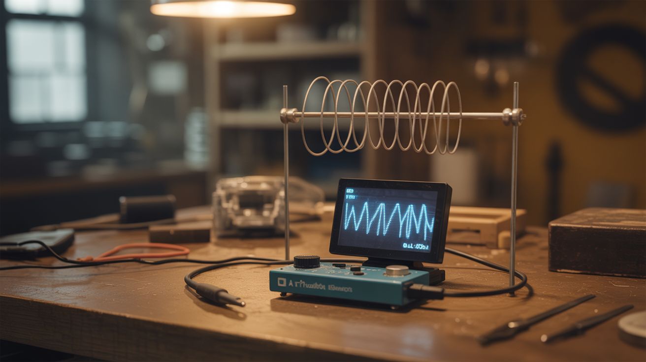
A wire antenna and Arduino read electromagnetic field fluctuations on an OLED display — market as a ghost detector for Halloween.
Ratings
🧪 What Is It?
Electromagnetic fields are everywhere — power lines, appliances, phone signals, even your own body generates tiny electrical fields. An Arduino with a long wire antenna can detect these fields through capacitive coupling. The wire picks up ambient EMF, and the Arduino's ADC reads the fluctuations. Display the readings on an OLED screen with a needle gauge graphic, add some spooky sound effects through a buzzer, and you've got a "ghost detector" that actually responds to real electromagnetic phenomena. It beeps near electronics, spikes near power outlets, and fluctuates when people wave their hands near it. Perfect for Halloween, escape rooms, or just freaking out your friends. The device is real science packaged as entertainment.
🧰 Ingredients
- Arduino Nano (electronics supplier)
- Wire — 6-12 inches of solid core wire for the antenna (junk drawer)
- 0.96" OLED display — I2C, SSD1306 (electronics supplier)
- Buzzer — piezo, for audio feedback (electronics supplier)
- LED — red or green for visual indicator (electronics supplier)
- 10M ohm resistor — pull-down for the antenna input (electronics supplier)
- 9V battery + clip (grocery store)
- Project enclosure — something spooky-looking works best (thrift store, dollar store)
- Toggle switch — power on/off (electronics supplier)
🔨 Build Steps
- Build the antenna circuit. Connect a 6-12 inch wire to an Arduino analog input pin. Connect a 10M ohm resistor from the same pin to ground — this is the pull-down that gives the floating antenna a reference point. The wire acts as a capacitive antenna, picking up ambient electromagnetic fields.
- Wire the OLED display. Connect the SSD1306 OLED to the Arduino via I2C (A4=SDA, A5=SCL). Install the Adafruit SSD1306 and GFX libraries. Test with a basic display sketch.
- Write the EMF reading code. Read the analog input rapidly (take 100 samples in quick succession), calculate the peak-to-peak voltage swing. This represents the EMF strength. Higher swing = stronger field. Map this to a 0-100 scale for display.
- Create the display graphics. Draw a needle gauge on the OLED: a semicircle with markers from "QUIET" to "ACTIVE" to "DANGER." Animate the needle based on the EMF reading. Add a numeric readout and a waveform graph showing readings over time.
- Add audio feedback. Wire a piezo buzzer to a digital pin. Map the EMF reading to buzzer frequency — low readings produce slow, quiet clicks. High readings produce rapid, higher-pitched beeping. The classic EMF detector sound is a click rate proportional to field strength.
- Calibrate baseline. Take readings in a quiet area (away from electronics and wiring) to establish the noise floor. Set this as your zero point. Readings above noise floor indicate real EMF sources.
- Test near known sources. Wave the antenna near a phone (strong spike during calls), microwave (massive field), power outlets (60Hz hum), and people (weak bio-electric field). Verify the detector responds to all of these.
- Package for maximum spookiness. Mount in a project box that looks old or mysterious. Label it with pseudo-scientific terms. Add a flickering LED. The presentation is half the fun — the more "authentic" it looks, the more people buy into the experience.
⚠️ Safety Notes
- This is an entertainment device, not a scientific instrument. EMF readings correlate with real electromagnetic sources (electronics, wiring, motors), not supernatural phenomena. Don't let anyone make health decisions based on its readings.
- The long wire antenna can build up static charge, especially in dry conditions. Touching the antenna tip to a sensitive component can discharge static and damage it. Handle by the insulated base.
- Keep the antenna away from mains voltage outlets and exposed wiring. While the detection circuit is safe, physically contacting live electrical with the wire creates a shock hazard.