#338 — Mechanical Flip-Dot Display
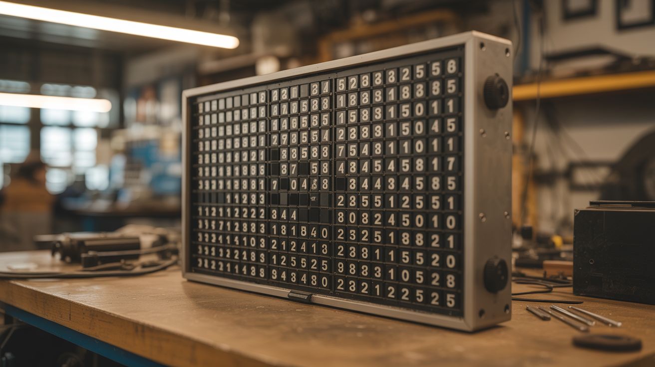
A grid of 256 electromagnetic pixels that physically flip between black and yellow with a deeply satisfying cascading CLICK — the soul of old airport departure boards, built from scratch.
Ratings
🧪 What Is It?
A flip-dot display is a mechanical pixel matrix where each "pixel" is a small physical disc painted one color on the front (yellow) and another on the back (black). Each disc is mounted on a pivot with a tiny permanent magnet attached. Below each disc sits a hand-wound electromagnetic coil. Pulse the coil one direction and the magnet snaps the disc to show yellow. Reverse the pulse and it flips to black. The disc stays in position with no power — the permanent magnet holds it against a stop. Power is only needed at the moment of transition.
When you update the display, 256 little discs flip in rapid succession, producing a cascading mechanical CLICK that is one of the most satisfying sounds in the maker world. It's the sound of old train station departure boards, bus route signs, and airport gate displays — physical, tactile information that people instinctively stop to watch. In the age of silent OLED screens, a flip-dot display is aggressively analog and people cannot look away.
A 16x16 grid gives you 256 pixels — enough for text, simple graphics, animations, and live data feeds. An Arduino drives a chain of shift registers that address each pixel individually. Feed it weather data, RSS headlines, the time, pixel art, or Conway's Game of Life. Every update sounds like a tiny round of applause.
🧰 Ingredients
- Magnet wire (28-32 AWG enamel-coated copper) — for winding 256 electromagnetic coils (source: dead transformers — unwinding one microwave or power supply transformer yields hundreds of feet, free)
- Small neodymium magnets (3-5mm disc) x 256 — one per pixel (source: dead hard drives contain 2 strong magnets each, plus online bulk packs, ~$10)
- Pivot pins or short lengths of 1mm steel wire — for the disc axles (source: sewing pins, paperclips, hardware store)
- Disc blanks — 10-15mm diameter, thin material painted yellow on one side and black on the other (source: sheet metal, plastic, or 3D-printed — $5-10 in material)
- Shift registers (74HC595) — 32 needed for 256 outputs (source: electronics supplier, ~$8 for 40-pack)
- H-bridge driver ICs (L293D or L298N) — to reverse coil polarity for bidirectional flipping (source: electronics supplier, ~$10)
- Arduino Mega or ESP32 — needs enough I/O for the shift register chain (source: online, ~$8-15)
- Frame material — plywood, acrylic, or 3D-printed grid panels for mounting the dot mechanisms (source: hardware store, scrap pile)
- Perfboard or custom PCB — for mounting shift registers and drivers (source: electronics supplier)
- 12V power supply, 3-5A — for driving coils (source: old laptop charger, ATX PSU)
- Wire, solder, headers, connectors (source: electronics bin)
🔨 Build Steps
-
Design and prototype a single flip mechanism. This is the critical step — get one pixel working perfectly before committing to 256. Each pixel needs: a disc on a pivot, a permanent magnet glued to the disc, and an electromagnetic coil positioned so its field can overcome the magnet's resting force and flip the disc. The disc should snap cleanly between two positions (yellow-up and black-up) with a satisfying click against the stops. Spend real time here. The geometry, coil winding count, and magnet placement all interact.
-
Wind the electromagnetic coils. Each coil needs 80-150 turns of 30 AWG magnet wire around a small former (a nail, bolt, or 3D-printed bobbin about 5mm diameter). Wind them by hand or rig a slow drill press as a winding jig. 256 coils is a lot of winding. Put on a podcast. Each coil should measure 5-20 ohms — consistency matters more than hitting an exact number. Salvaging wire from dead transformers is the move — one MOT secondary yields enough wire for the whole display.
-
Build the disc assemblies. Cut or punch 256 discs from thin sheet metal, plastic, or 3D-print them. Paint or apply vinyl — yellow one side, black the other. Glue a small neodymium magnet to the edge of each disc, oriented so the magnet interacts with the coil. Press-fit each disc onto a pivot pin. The pivot should have minimal friction — the disc needs to flip from a brief electromagnetic pulse, not a sustained push.
-
Test the single-pixel prototype. Wire the coil to a momentary switch through an H-bridge (or just swap battery leads by hand). The disc should flip decisively in both directions with a clean click. If it's sluggish, add more turns to the coil, use a stronger magnet, or reduce pivot friction. If it flips but won't stay, reposition the permanent magnet or add a small mechanical detent.
-
Scale to a row of 16. Build a mounting frame (laser-cut, 3D-printed, or drilled from thin plywood) that holds 16 pixel mechanisms in a straight row with consistent spacing. Wire all 16 coils to a shift register feeding into H-bridge drivers. Write Arduino code that can address and flip any pixel in the row independently.
-
Build the shift register driver circuit. Chain 32 shift registers (74HC595, serial-in parallel-out) in series — the Arduino clocks out 256 bits of data via SPI (MOSI to data-in, SCK to clock, latch pin shared). Data propagates down the chain at up to 1 MHz, so a full 256-bit frame update takes <1ms. Each shift register output drives an H-bridge channel (L293D or L298N) that controls one coil. The H-bridge allows you to pulse each coil in either direction (flip to yellow or flip to black). Build this on perfboard or order a small PCB run. Test each channel before assembling the full grid.
-
Assemble the full 16x16 grid. Stack 16 rows into a grid. Mount them in a rigid frame with consistent spacing. This is cabinetry-level work — misaligned rows look terrible and the whole display is on view. Clamp everything square before fastening. Route coil wires to the back and connect each to its shift register channel. Label everything. 256 connections with no labeling system is a nightmare you don't come back from.
-
Write the Arduino firmware. The firmware needs to: (a) accept pixel data over serial or WiFi, (b) compare new frame data to current pixel states (only flip pixels that changed — this saves power and sounds better), (c) clock out the shift register data, and (d) pulse the H-bridges for the correct duration. A 5-15 ms pulse per pixel is typical. You can flip all changed pixels simultaneously for a dramatic full-frame clack, or cascade them column-by-column for that classic departure-board ripple.
-
Implement font rendering. Store bitmap fonts in the firmware — a 16-pixel-tall font lets you display 1-2 lines of text. Write a text-rendering function that converts ASCII strings to pixel maps. Scrolling text is the classic flip-dot application: shift the pixel buffer left by one column, append the next column of the next character, and update the display. The cascading click of scrolling text is hypnotic.
-
Add serial or WiFi input for live data. Connect the Arduino's serial port to a computer, or use an ESP32 for WiFi. Write a simple protocol: send a 256-bit frame (or text string) over serial/WiFi and the display updates. From the computer side, a Python script can pull weather data, RSS feeds, social media mentions, clock time, or anything else and push it to the display. Live-updating flip-dot displays are irresistible — people will stand and watch for minutes.
-
Build the frame and mounting. Construct a finished frame from wood, metal, or acrylic. The frame hides all the wiring on the back while presenting the pixel grid flush on the front. Wall-mount brackets let you hang it like art. A slight tilt (5-10 degrees forward) improves visibility from below. The back panel should be removable for maintenance access.
-
Calibrate and test every pixel. Run a test pattern that flips every pixel in sequence — all yellow, all black, checkerboard, diagonal sweep. Identify and fix any stuck, sluggish, or intermittent pixels. Common fixes: re-solder a loose coil connection, add a drop of oil to a sticky pivot, adjust a magnet that shifted during assembly. A display with even one dead pixel is annoying. Get them all working.
⚠️ Safety Notes
[!WARNING] Coil winding tedium is real. 256 coils at 100+ turns each is 25,000+ turns of wire. Budget your time and your patience. Wind in batches, test as you go, and accept that some coils will need to be rewound.
- Inductive voltage spikes. Electromagnetic coils produce voltage spikes when switched off rapidly. The H-bridge drivers handle this, but if you're prototyping with bare MOSFETs or transistors, add flyback diodes across every coil or you'll fry your driver ICs. This is not optional.
- Soldering volume. 256 coils, each with 2 connections, plus shift register chains and H-bridge wiring — you're looking at 600+ solder joints. Use proper ventilation, take breaks, and don't rush. A cold solder joint buried in the middle of the grid is extremely annoying to diagnose.
- Power supply sizing. If all 256 coils pulse simultaneously, the current draw spikes hard. Size your power supply with headroom (3-5A at 12V minimum) and add a bulk capacitor (1000uF+) near the driver boards to absorb transient loads.
🔗 See Also
- LED Cube 8x8x8 — another large-scale pixel display project, but with LEDs instead of mechanical dots
- Pen Plotter — mechanical precision meets visual output in a different form factor